Left Atrial Intraprocedural Radial ICE Guidance:
Transseptal Punctures can be safely performed using radial ICE guidance. A suitably sized Mullins introducer sheath (10-11 French) can be used to position the radial ICE catheter along the interatrial septum as shown in Figure 1. The Mullins sheath provides enough maneuverability to adjust the ICE catheter position in both inferior-superior and anterior-posterior directions to optimize the location of transseptal puncture in the fossa ovalis. Once ICE localization of transseptal needle showing tenting of the septum in suitable fossa is obtained LAO fluoroscopy is then used to guide the transseptal puncture and advancement of left atrial sheath.

Figure 1 Radial ICE Guidance of Transseptal Puncture for Left Atrial Access. The left and right atria are well-visualized with the ICE catheter in the right atrium along the interatrial septum in the fossa ovalis. One can see the tenting evident when transseptal needle is in good contact with the interatrial septum.
Left Atrial Ablations can be enhanced and accomplished using intra left atrial radial ICE (with intraprocedural heparinization for ACT>300). [1,2,3] Radial ICE is a useful adjunct imaging technique for several reasons. First, direct visualization of the electrode-endocardial interface allows precise positioning of the ablation electrode to guide lesion formation. Second, radial ICE permits the delivery of “focal” left atrial ablative lesions; the electrode kept in same location throughout energy application by manipulating the ablation electrode into firm, stable endocardial contact during continuous ICE imaging of the electrode–endocardial interface. Third, the use of continuous radial ICE during atrial fibrillation ablations allows close monitoring of catheter position and endocardial contact while minimizing dependence on fluoroscopy. Figure 2 depicts a typical view obtained when radial ICE is positioned in the left atrium using a steerable sheath (Agilis, St. Jude Medical, Inc., St. Paul, MN).

Figure 2 Intra Left Atrial Radial ICE Imaging During Atrial Fibrillation Ablation Left Pulmonary Venous Antrum Isolation. The radial ICE catheter is positioned at the entrance to the left PV antrum with the tip of the ablation catheter (Thermocool irrigated tip, Biosense Webster Inc, Diamond Bar, CA) located at ~9 o’clock on the antrum. The inset shows the analogous location of ablation catheter on 3D CT reconstruction of the left PV antrum.
Detailed anatomy of the pulmonary veins can also aid in catheter positioning and stability as well as monitor for procedural complications (discussed later). Figure 3 provides views of the left and right pulmonary vestibules. The left upper (LUPV) and lower pulmonary veins (LLPV) are visualized as are the saddles. The right intervenous saddle is not as clearly differentiated as the left in this particular example to give the reader a better overall view of the structures surrounding the right pulmonary vestibule such as SVC, main PA, and Waterston’s groove (WG). Waterston’s groove is a fat-filled depression formed as the left and right atria fold into one another; Waterston’s groove is often dissected by surgeons to expose the left atrium. Radial ICE can be carefully placed within each individual pulmonary veins to guide catheter ablation as previously described. [1,2,3]
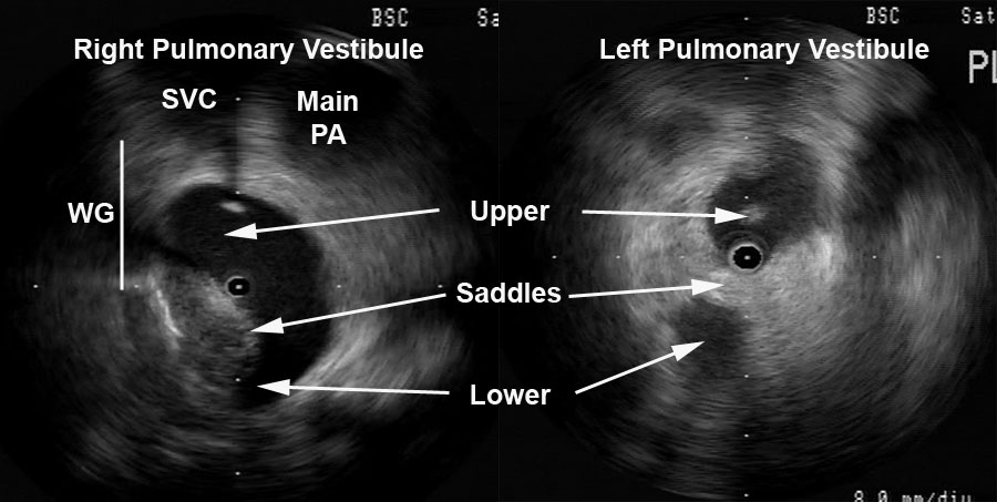
Figure 3 Radial ICE Anatomy of Left and Right Pulmonary Vestibules. The right pulmonary vestibule is shown with the early portions of the upper and lower pulmonary veins. Superior to the right pulmonary veins one can see the main pulmonary artery and superior vena cava. The approximate location of Waterston’s groove is depicted by the solid line. A more distal view of the left pulmonary vestibule (compared to Figure 2) clearly differentiates the upper and lower PV’s as well as the intervenous saddle.
Radial ICE can also help guide linear ablation along the LA posterior wall for mitral annular flutter. Direct visualization of the left lower pulmonary vein, the posterior wall of the LA, the mitral annulus, and CS during ablation (both intra LA and CS) can improve catheter contact allowing for complete linear ablation and bidirectional block (see Figure 4).

Figure 4 Ablation Near Mitral Annulus. A depicts the intra-LA radial ICE catheter with ablation catheter along the floor of left atrium near mitral annulus. B shows a similar view demonstrating the ablation catheter in the CS. Endocardial (and CS) contact and possible ablation injury can be visualized during lesion delivery.
Note: This is adapted from work I did with Dr. Sheetal Chandhok.
References:
1 Schwartzman D, Nosbisch J, Housel D. Echocardiographically guided left atrial ablation: characterization of a new technique. Heart Rhythm, V. 3 (2006), pp. 930–938.
2 Schwartzman D, Williams JL, “On the Electroanatomic Properties of Pulmonary Vein Antral Regions Enclosed by Encircling Ablation Lesions,” Europace , V. 11 (2009), pp. 435–444.
3 Chandhok S, Williams JL, Schwartzman DS, “Anatomical analysis of recurrent conduction after circumferential ablation,” J Intervent Card Electrophysiol, V. 27, No. 1 (January 2010), pp. 41-50.

One thought on “Part 2 Radial Intracardiac Echocardiography in the EP Lab: Left Atrial Procedures”