Both non-irrigated and irrigated tip catheters for radiofrequency ablation (RFA) can cause steam pops with abrupt impedance rises probably owing to release of steam from excessive heating below the surface. [1] Saline irrigation maintains a low electrode-endocardial interface temperature during RFA at higher powers, which prevents an impedance rise and produces deeper and larger lesions. But you can see higher temperatures deeper in the cardiac wall (~3.5mm) than at the electrode-endocardial interface. This is thought to be due to direct resistive heating rather than by conduction of heat from the surface. [1] This excessive heating may cause water in the endocardium to vaporize into a gas bubble. Continued ablation (and hence heat formation) can cause this bubble to expand with increased pressure. If this gas bubble suddenly bursts inward toward the endocardium or outward to the epicardium, it can cause an audible “pop.”
The following video (courtesy of Dr. Dave Schwartzman, UPMC, Pittsburgh, PA) shows an ex vivo tissue preparation and formation of a steam pop during application of RFA. A significant concern of steam pops is the risk of cardiac perforation. Perforation with tamponade was seen in 1 of 62 (2%) VT ablations where a steam pop occurred. [2] The RFA applications with steam pops had a higher maximum power but did not differ in maximum catheter tip temperature. It reasons that steam pops in the pulmonary veins or atria may pose higher risk of perforation.
A middle-aged male with no significant medical history underwent an EP study and ablation for typical atrioventricular node reentrant tachycardia (AVNRT). The AVNRT ablation was being guided by radial intracardiac echocardiography. RFA (using power-control setting) is attempted at the anatomic location of the slow AVN pathway region at the anterior edge of the CS os near the septal insertion of the tricuspid valve leaflet (see Figure). Power was titrated from 5W to 30W but required 40W to demonstrate an accelerated junctional rhythm associated with ablation success. A steam pop was felt and evidence of a small defect in the endocardium in the region was noted on radial ICE as shown in Figure. There was no obvious microbubble formation evident on radial ICE prior to the steam pop. Subsequent echocardiograms demonstrated no evidence of perforation or tamponade and patient was asymptomatic at follow-up several weeks later.
Radial ICE showing the anatomic location of the slow AVN pathway and effects of a steam pop after RFA.
References:
1 Nakagawa H et al, “Comparison of In Vivo Tissue Temperature Profile and Lesion Geometry for Radiofrequency Ablation With a Saline-Irrigated Electrode Versus Temperature Control in a Canine Thigh Muscle Preparation,” Circulation (1995), V. 91, pp. 2264-2273.
2 Seiler J et al, “Steam pops during irrigated radiofrequency ablation: feasibility of impedance monitoring for prevention,” Heart Rhythm (Oct 2008), V. 5, No. 10, pp. 1411-1416.
Radial ICE (UltraICE™, Boston Scientific, Natick, MA, USA) uses a mechanical, 9 Fr, 9 MHz catheter, with 360° radial image. The ultrasound transducer rotates every 1.4° and with full mechanical rotation of the transducer (hence, 256 stacked lines of ultrasound data), a panoramic 360° image is created that is perpendicular to the catheter shaft at the tip. Radial ICE does not offer doppler capability and image definition is not as good as phased array ICE. Radial ICE’s 360° scan has a larger field of view and allows for a more comprehensive depiction (compared to phased array) of both atrial chambers and atrioventricular valves with their relationships and it also can be used as intravascular ultrasound for great vessels. Phased-array 8 French, 4.5–11.5 MHz catheter (AcuNavTM Ultrasound Catheter, Biosense Webster Inc., Diamond Bar, CA) has a 90° sector image, Doppler capability, and is deflectable. Radial ICE’s mechanical transducer is a non-deflectable catheter thus a steerable sheath (Zurpaz 8.5F Steerable Sheath, Boston Scientific Corporation, Natick, MA or Agilis, St. Jude Medical, St. Paul, MN) is required for precise catheter movements beyond transseptal puncture guidance.
Basic Cardiac Anatomy:
Figure 1 depicts the basic cardiac anatomy revealed with radial ICE and the analogous fluoroscopic views. The high SVC view permits view of the SVC and ascending aorta and the PA comes into view as one moves inferiorly towards the low SVC. The mid RA view tends to be the most useful view for orienting oneself in the right heart and (as discussed later) is the most useful view for transseptal access into the left atrium. The low RA view is useful for delineating complex IVC and CS anatomy.
Figure 1 Basic Cardiac Anatomy with Radial Intracardiac Echocardiography (ICE).
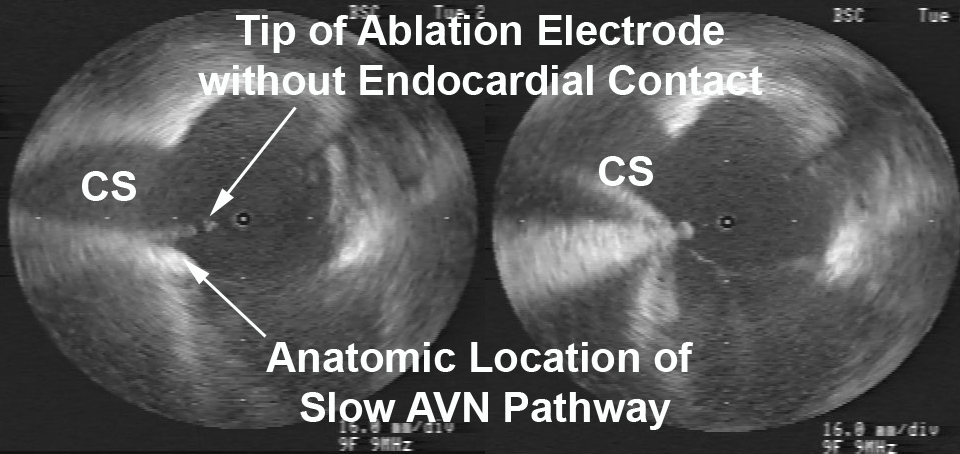
AV Node Reentrant Tachycardia requires careful catheter manipulation to modify the slow AV node pathway. Traditionally, slow AV node pathway modification is guided by fluoroscopic images and electrogram morphology. Radial ICE-guided AVNRT ablation has been well-described by Fisher et al. [1] Figure 2 depicts the radial ICE anatomy of the slow AVN pathway during an ablation for AVNRT. In this case, the patient had a persistent left superior vena cava (SVC) and ablation at attractive electrograms using fluoroscopic guidance did not yield a successful ablation.
Figure 2 Radial ICE Guidance during AVNRT Ablation of the Slow AV Node Pathway.
Figure 2 Radial ICE Guidance during AVNRT Ablation of the Slow AV Node Pathway. The left image depicts initial ablation catheter not in contact with the endocardial location of slow AVN pathway. The right image clearly depicts adequate electrode-endocardial contact which resulted in a successful ablation.
Radial ICE imaging was then used (with ICE catheter directional guidance via steerable sheath) to anatomically guide the ablation electrode to the slow AVN pathway which is located in the region at the anterior edge of the CS os near the septal insertion of the tricuspid valve leaflet (e.g., the anterior border of triangle of Koch). The left image shows the initial ablation catheter position and clearly demonstrates the electrode is not in contact with the endocardium. Ablation catheter manipulation to the location depicted in the right image led to an immediately successful ablation. Radial ICE guidance during AVNRT ablations allows one to visualize and ensure catheter stability during the ablation to avoid accidental catheter migration as compared to fluoroscopy which does not permit one to constantly monitor the electrode-endocardial interface.
AV Node Ablation can generally be performed under RAO and LAO fluoroscopic guidance however, there are times when the compact AV node cannot be ablated using traditional right atrial ablation techniques or only right bundle branch block can be obtained. Radial ICE can be used to complete AV node ablation by catheter guidance to the leftward extension of the His purkinje system prior to attempting a retrograde aortic approach to AV node ablation (which often requires an 8 French right femoral arterial sheath). Figure 3 depicts a typical site where complete heart block can be obtained by ablating more proximate to the leftward extension of the His bundle.
Figure 3 Completion of AV Nodal Ablation under Radial ICE Guidance.
Figure 3 Completion of AV Nodal Ablation under Radial ICE Guidance. This figure depicts radial ICE catheter location in the RVOT near the level of aortic valve. The radial ICE allows catheter position nearer to the leftward extension of the His purkinje system in an attempt to complete AV node ablation.
Radial ICE can be used for detailed assessment of RA anatomy especially during mapping of difficult atrial tachycardias. Figure 4 shows the level of RA detail radial ICE can provide to assist EP study catheter localization.
Figure 4 Radial ICE Assessment of RA Anatomy. Figure from Springer, Journal of Interventional Cardiac Electrophysiology
Figure 4 Radial ICE Assessment of RA Anatomy. Right atrial anatomy is nicely visualized with radial ICE and corresponding anatomic specimen. One can see how adjunctive imaging during difficult RA ablation may help visualize catheter position and endocardial contact. Figure taken from Springer, Journal of Interventional Cardiac Electrophysiology [2].
Oftentimes, catheter access of the CS can be difficult due to anatomic variants involving both the Eustachian ridge (when using femoral venous access) and Thebesian valves. The Eustachian valve continues superiorly from the IVC as the Tendon of Todaro that forms the Eustachian ridge (forming the superior aspect of the triangle of Koch). [3] Additionally, prior reviews of CS anatomy (4) revealed the presence of Thebesian valves (rudimentary valve covering CS os) in 80% of cases. It covered one-fifth in 7%, one-third the os in 29%, one-half in 27%, two-thirds in 14%, and the entire os in 5%. Figure 5 depicts radial ICE imaging of both anatomic variants. A minimally fenestrated Thebesian valve can make CS access unfeasible as in this case. A prominent Eustachian ridge can mandate CS access using a subclavian or jugular venous approach as it often impedes catheter placement when using a femoral venous approach.
Figure 5 Radial ICE Imaging of CS Anatomic Variants.
Figure 5 Radial ICE Imaging of CS Anatomic Variants. The left image shows a Thebesian valve with no obvious fenestrations covering the CS os. The right image shows a prominent Eustachian ridge extending from the IVC and overlying the superior aspect of the CS os.
Check Back for:
Part 2 Radial Intracardiac Echocardiography in the EP Lab: Left Atrial Procedures
Part 3 Radial Intracardiac Echocardiography in the EP Lab: Monitoring Procedural Complications
Part 4 Radial Intracardiac Echocardiography in the EP Lab: Electroanatomic Correlates During Radial ICE
Note: This is adapted from work I did with Dr. Sheetal Chandhok.
References:
1 Fisher WG, Pelini MA, Bacon ME, “Adjunctive Intracardiac Echocardiography to Guide Slow Pathway Ablation in Human Atrioventricular Nodal Reentrant Tachycardia: Anatomic Insights,” Circulation, V. 96 (1997), pp. 3021-3029.
2 Morton JB and Kalman JM, “Intracardiac Echocardiographic Anatomy for the Interventional Electrophysiologist,” J Int Cardiac Electrophysiology, V. 13 (2005), pp. 11-16.
3 Ho SY and Ernst S, Anatomy for Cardiac Electrophysiologists (2012; Cardiotext Publishing, LLV, Minneapolis, MN).
4 Pejkovic B, Krajnc I, Anderhuber F, Kosutic D, “Anatomical Variations of the Coronary Sinus Ostium Area of the Human Heart,” J Int Med Research, V. 36 (2008), pp. 314-321.