Atrial fibrillation ablations can be accomplished using radial intracardiac echocardiographic (ICE) guidance and can help minimize fluoroscopic use. ICE imaging is initially used during left-sided ablations by facilitating transeptal punctures. Next, radial ICE can be placed in the left atrium to guide atrial fibrillation ablations and demonstrate stable ablation electrode-endocardial contact. Clearly, contact force-sensing ablation catheters have helped assess electrode-endocardial contact but radial ICE allows the operator to directly visualize contact. Furthermore, direct ICE visualization permits assessment of endocardial tissue deflection as well as anatomic guidance to help make left-sided ablations safer (e.g., location of esophagus, thickness of left atrial regions, etc). A full description of radial ICE-guided atrial fibrillation ablation has been previously described (1,2,3) but we will take a more detailed ICE tour of the ablative process.
Radial ICE Guided Transeptal Puncture:
Transseptal Punctures can be safely performed using radial ICE guidance. A suitably sized Mullins introducer sheath (10-11 French) can be used to position the radial ICE catheter along the interatrial septum as shown in Figure 1. The Mullins sheath provides enough maneuverability to adjust the ICE catheter position in both inferior-superior and anterior-posterior directions to optimize the location of transseptal puncture in the fossa ovalis. Once ICE localization of transseptal needle showing tenting of the septum in suitable fossa is obtained LAO fluoroscopy is then used to guide the transseptal puncture and advancement of left atrial sheath.

Figure 1 Radial ICE Guidance of Transeptal Puncture for Left Atrial Access. The left and right atria are well-visualized with the ICE catheter in the right atrium along the interatrial septum in the fossa ovalis. One can see the tenting evident when transseptal needle is in good contact with the interatrial septum.
The following video shows the interatrial septum with radial ICE located in the right atrium. You see tenting of the septum and subsequent transeptal puncture facilitating left atrial ablation. Once transeptal access is achieved using an 8F Mullins sheath, a long wire exchange is performed to allow placement of the steerable sheath through which radial ICE is placed. An additional transeptal puncture is performed and wire exchange placement of 8.5Fr SRO sheath through which an irrigated tip ablation catheter is placed.
Appearance of Radial ICE to Guide Transseptal Punctures
Intra Left Atrial Radial ICE:
Left Atrial Ablations can be enhanced and accomplished using intra left atrial radial ICE (with intraprocedural heparinization for target ACT>300). [1,2,3] Radial ICE is a useful adjunct imaging technique for several reasons. First, direct visualization of the electrode-endocardial interface allows precise positioning of the ablation electrode to guide lesion formation. Second, radial ICE permits the delivery of “focal” left atrial ablative lesions; the electrode kept in same location throughout energy application by manipulating the ablation electrode into firm, stable endocardial contact during continuous ICE imaging of the electrode–endocardial interface. Third, the use of continuous radial ICE during atrial fibrillation ablations allows close monitoring of catheter position and endocardial contact while minimizing dependence on fluoroscopy. Figure 2 depicts a typical view obtained when radial ICE is positioned in the left atrium using a steerable sheath (Agilis, St. Jude Medical, Inc., St. Paul, MN).

Figure 2 Intra Left Atrial Radial ICE Imaging During Atrial Fibrillation Ablation Left Pulmonary Venous Antrum Isolation. The radial ICE catheter is positioned at the entrance to the left PV antrum with the tip of the ablation catheter (Thermocool irrigated tip, Biosense Webster Inc, Diamond Bar, CA) located at ~9 o’clock on the antrum. The inset shows the analogous location of ablation catheter on 3D CT reconstruction of the left PV antrum.
Detailed anatomy of the pulmonary veins can also aid in catheter positioning and stability as well as monitor for procedural complications. Figure 3 provides views of the left and right pulmonary vestibules. The left upper (LUPV) and lower pulmonary veins (LLPV) are visualized as are the saddles. The right intervenous saddle is not as clearly differentiated as the left in this particular example to give the reader a better overall view of the structures surrounding the right pulmonary vestibule such as SVC, main PA, and Waterston’s groove (WG). Waterston’s groove is a fat-filled depression formed as the left and right atria fold into one another; Waterston’s groove is often dissected by surgeons to expose the left atrium. Radial ICE can be carefully placed within each individual pulmonary veins to guide catheter ablation as previously described. [1,2,3]
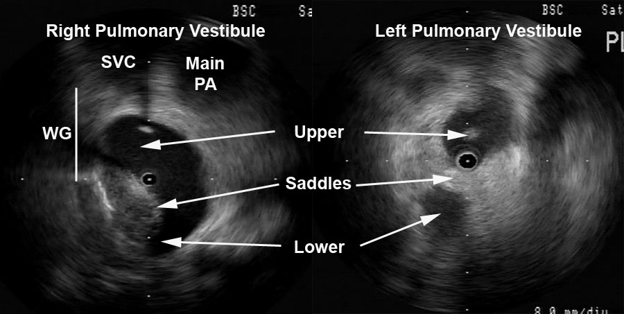
Figure 3 Radial ICE Anatomy of Left and Right Pulmonary Vestibules. The right pulmonary vestibule is shown with the early portions of the upper and lower pulmonary veins. Superior to the right pulmonary veins one can see the main pulmonary artery and superior vena cava. The approximate location of Waterston’s groove is depicted by the solid line. A more distal view of the left pulmonary vestibule (compared to Figure 2) clearly differentiates the upper and lower PV’s as well as the intervenous saddle.
Intra Left Atrial ICE-Guided Atrial Fibrillation Ablation via Wide Pulmonary Venous Antrum Isolation:
Left Pulmonary Venous Antrum Isolation
Once double transeptal access is obtained, the posterior left atrium pulmonary antrum isolation is started. I generally create a Fast Anatomic Mapping (FAM and CARTO, Biosense Webster, Inc., Diamond Bar, CA) shell of the left atrium trying to capture the anatomy of the left and right pulmonary veins to accurately recreate similar anatomy from the preoperative CT scan. This FAM shell is a complement to the real-time radial ICE that actually guides my ablation catheter placement. The left pulmonary vestibule is first encircled by placing a series of focal lesions applied contigously. Ablation is performed during sinus rhythm. High-frequency ventilation is used to minimize posterior LA motion. Each encircling lesion is composed of a series of contiguously applied (defined by direct contact of adjacent CARTO icons) “focal” (e.g., electrode kept in same location throughout energy application) lesions. For each focal lesion, the ablation electrode is manipulated under ICE guidance into firm, stable endocardial contact. RF energy was delivered during continuous ICE imaging of the electrode–endocardial interface.
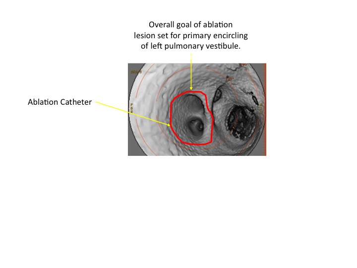
The following video shows catheter position while ablating the posterior aspect of the left pulmonary vestibule. Note the appearance of “bubbles;” this is saline irrigation during ablation. The 3D reconstructions CT scan below the video shows the approximate site of ablation catheter and the overall goal ablative lesion set pathway for the primary encircling of the left pulmonary vestibule.
After deployment of this primary line of encircling lesion, I document that the myocardium subtended by the lesion is electrically isolated using entrance and exit block criteria. The radial ICE catheter is then placed into the left upper pulmonary vein (LUPV) and entrance block is assessed by examining pulmonary vein (PV) potentials; PV potentials in the LUPV are ablated down to the first branch of the LUPV. Exit block is assessed by unipolar pacing from the ablation catheter; any LUPV capture site is ablated as I pull back toward the primary encircling lesion set. The following video shows the ICE catheter inserted into the LUPV with an esophageal probe at 11AM and the ablation catheter at 5PM. The course of the esophagus is a bit unusual in this case and clearly lower power ablative lesions are carefully delivered (and sometimes deferred) to minimize the risk of esophageal damage.
If entrance and exit block are not documented secondary lesions are placed within the primary line to obtain isolation. One can see that radial ICE is used to guide ablation catheter position, maintain catheter stability, and watch for any endocardial damage (such as “heaping”). Once LUPV lesions (if necessary) are completed, the ICE catheter is moved into the LLPV and the PV potential mapping/ablation process is repeated as above. The following video shows the ICE catheter being moved from the LUPV into the LLPV.
The following video shows mapping in the LLPV down to the first branch of the LLPV that is evident on ICE.
After the left pulmonary antrum is isolated, this procedure is repeated for the right pulmonary antrum.
Right Pulmonary Venous Antrum Isolation
Figure 3 depicts still frames of the pulmonary venous antrums. The following video shows a typical view of the right pulmonary venous antrum. The initial portion shows a real-time view of the right pulmonary venous antrum and then the ICE catheter is advanced into the RUPV; towards the end of the video you can see the ablation catheter enter the RUPV and located at the roof ~12P.
Similar to the left pulmonary venous antrum, the right pulmonary vestibule is first encircled by placing a series of focal lesions applied contigously. After deployment of this primary line of encircling lesion, I document that the myocardium subtended by the lesion is electrically isolated using entrance and exit block criteria. The radial ICE catheter is then placed into the right upper pulmonary vein (RUPV) and entrance block is assessed by examining pulmonary vein (PV) potentials; PV potentials in the RUPV are ablated down to the first branch of the RUPV. Exit block is assessed by unipolar pacing from the ablation catheter; any RUPV capture site is ablated as I pull back toward the primary encircling lesion set. Once RUPV lesions (as necessary) are completed, the ICE catheter is moved into the RLPV and the PV potential mapping/ablation process is repeated as above. The following video shows the ICE catheter being moved from the RUPV into the RLPV.
Ultimately, a complete right and left pulmonary venous antrum isolation is completed. The final figure below shows a typical final CARTO lesion set with the analogous course of ablative lesions (including ablation within the pulmonary veins) shown on the 3D CT reconstruction.

Summary:
Left and right pulmonary venous antrum isolation can be completed using intra left atrial radial ICE guidance with the complementary use of 3D intracardiac mapping. The radial ICE ensures stable endocardial contact and guides catheter/lesion placement. In addition, real-time radial ICE guidance can enhance safety by highlighting esophageal location as well as provide electroanatomic correlation.
Note: Many thanks to my mentor Dr. David Schwartzman who took the time to teach me radial ICE and atrial fibrillation ablations!
References:
1 Schwartzman D, Nosbisch J, Housel D. Echocardiographically guided left atrial ablation: characterization of a new technique. Heart Rhythm, V. 3 (2006), pp. 930–938.
2 Schwartzman D, Williams JL, “On the Electroanatomic Properties of Pulmonary Vein Antral Regions Enclosed by Encircling Ablation Lesions,” Europace , V. 11 (2009), pp. 435–444.
3 Chandhok S, Williams JL, Schwartzman DS, “Anatomical analysis of recurrent conduction after circumferential ablation,” J Intervent Card Electrophysiol, V. 27, No. 1 (January 2010), pp. 41-50.
